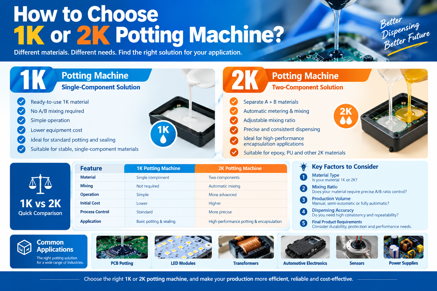
A two-component dispensing machine is designed to precisely meter, mix, and dispense two separate reactive materials (usually called Side A and Side B, such as epoxy, polyurethane, or silicone). These materials only begin to cure and harden once they are mixed together in the correct proportion.
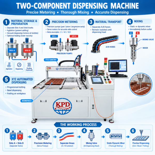
Here is the step-by-step working principle, breaking down how the machine manages the materials:
1. Material Storage and Preparation (Feeding System)
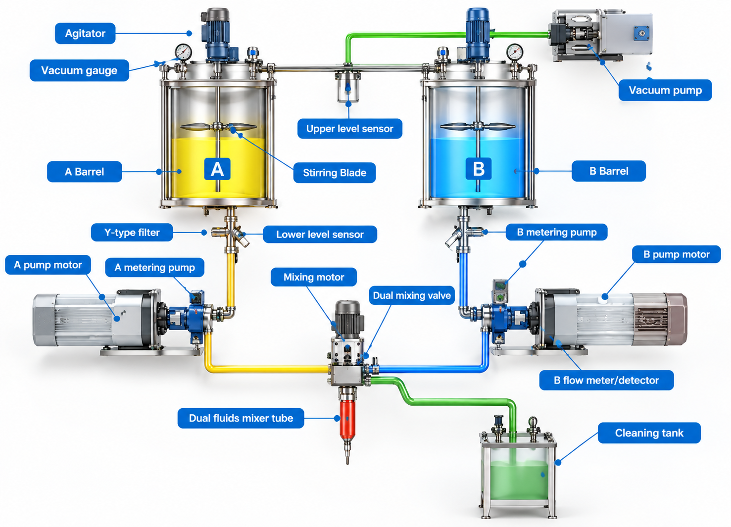
The process starts with the two separate components stored in separate tanks or reservoirs (often located behind or adjacent to the main machine frame seen in the image).
-
Degassing and Agitation: Before dispensing, many materials require preparation. The storage tanks often include agitators (to prevent fillers from settling) and vacuum degassing systems to remove entrapped air bubbles, which are critical for achieving void-free potting.
-
Heating (Optional): If the materials are highly viscous, the tanks and feed lines may be heated to lower the viscosity and improve flow.
2. Precision Metering (The Heart of the System)
This is the most critical stage. The machine must ensure that Side A and Side B are delivered in the exact ratio specified by the glue manufacturer (e.g., 1:1, 4:1, or 10:1 by volume or weight). The machine in your image uses precision pumps to achieve this. Common types include:
-
Gear Pumps: Highly common for continuous flow. Two meshing gears rotate, trapping a specific volume of material in the gaps between the gear teeth and the pump casing, transporting it precisely. The pump speed determines the output rate.
-
Piston Pumps: Excellent for abrasive materials or high-pressure applications. A piston moves within a cylinder, displacing a known volume of material with each stroke.
-
Progressive Cavity Pumps: Good for shear-sensitive materials and high-precision, pulsation-free dosing.
The pumps are driven by servo motors, allowing the machine’s control system to adjust the ratio and flow rate dynamically.
3. Material Transport and Valve Control
The metered materials are transported via separate, reinforced hoses (seen bundled within the black cable track in your image) to the dispensing head. Crucially, A and B remain separate until the very last moment to prevent premature curing inside the machine.
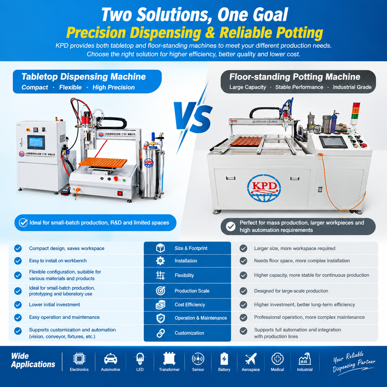
At the dispensing head, a specialized dispensing valve controls the flow. It acts as an on/off switch, precisely starting and stopping the flow to prevent dripping or tailing (the valve structure is located just above the brown mold in the photo).
4. Mixing (The Chemical Reaction)
Once Side A and Side B reach the valve outlet, they enter a mixer to begin the chemical reaction. There are two primary types of mixing used in industrial machines:
-
Static Mixing (Most Common): The materials are forced through a specialized plastic nozzle containing a series of fixed, helical elements. These elements repeatedly cut, fold, and re-combine the two material streams. By the time the material exits the nozzle, it is thoroughly mixed solely by the geometry of the static mixer. The nozzles are disposable, simplifying cleanup.
-
Dynamic Mixing: For extremely viscous materials or those with very challenging ratios, a motor-driven dynamic mixer is used. It features a spinning chamber that aggressively shears and blends A and B together.
5. Automated Positioning and Dispensing (The Robotic System)
The integrated XYZ Cartesian robotic system (the gantry structure inside the enclosure) positions the mixing nozzle precisely over the workpiece (the brown mold shown on the table).
-
Path Programming: The machine is programmed (via the touch screen control panel) to follow a specific path—dotting, drawing beads, or filling (potting) cavities—ensuring that the adhesive is applied exactly where needed and in the correct volume. The movement speed is synchronized with the pump speed to maintain a consistent bead profile.
Summary of the Cycle
-
Start Command: The operator initiates the program via the HMI (Touch Screen).
-
Move to Start: The XYZ gantry moves the dispensing head into position over the first target location.
-
Dispense: The control system activates the precision metering pumps (A and B start flowing in the correct ratio), opens the dispensing valve, and moves the gantry along the programmed path. The A and B materials mix thoroughly in the static or dynamic mixer nozzle right before exiting.
-
Stop: Upon completing the path, the valve closes, and the pumps stop.
-
Index/Repeat: The gantry moves to the next workpiece or location, repeating the process. If a batch is complete, the machine may move to a purge/cleaning station to prevent material from curing inside the mixer nozzle during idle time.